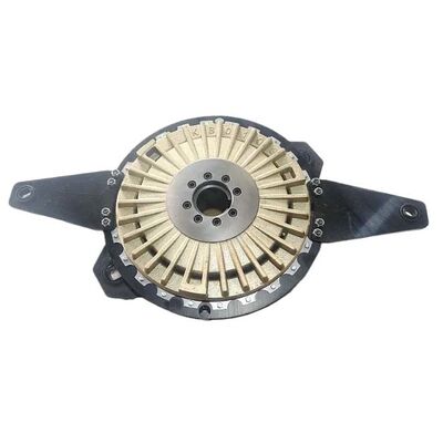
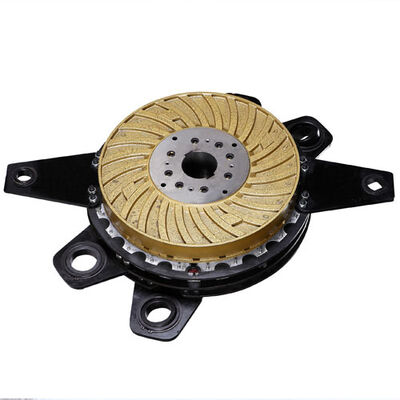
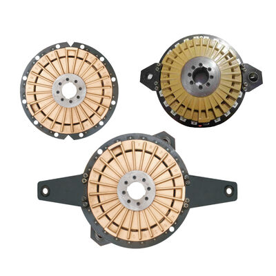
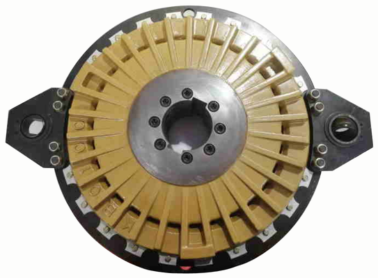
KB Series Air / Pneumatic Clutch Brake Combination
The KB series pneumatic friction clutch and brake combination unit is a good replacement for the OMPI PccU pneumatic clutch and brake combination unit.
They are similar in size and function, easy to use, and more economical.
The unit consists of a pneumatic clutch and brake, so the clutch and brake components can work together.
This KB-type pneumatic clutch and brake combination is commonly used in punch presses, die-cutting machines, cutting machines, and other forging equipment. In a die-cutting machine, air enters the clutch through the inlet, pushing the piston forward and compressing the liner. This, in turn, drives the drive shaft to rotate via the clutch base, engaging the clutch. When the air pressure is released, the piston moves backward under the action of a spring, compressing the liner again, disengaging the clutch; then the braking mechanism engages, stopping the rotating parts.
Feature:
-
The friction material is asbestos-free, making it safe and reliable.
-
Replacing the friction plates is simple and does not require disassembling the clutch.
-
The clutch ear plates come in a variety of configurations to suit different needs.
-
Suitable for industries such as stamping machines, forging machines, power presses, shearing machines, wood working machines,, textiles, cutting machines, ect.
Theory
The pneumatic clutch/brake combination unit consists of a pneumatic disc clutch and a spring-loaded disc brake. Its compact design, high thermal capacity, and low air consumption make it an ideal choice for high-speed, high-cycle, heavy-duty industrial applications. When the cylinder is pressurized, the piston clamps the clutch disc against the hub, thereby transmitting torque to the shaft. When the cylinder is vented, the spring moves the piston in the opposite direction, clamping the brake disc and bringing the shaft to a stop.
In the pneumatic clutch, the axial thrust required to establish torque is transmitted by the piston moving within the cylinder. When the cylinder chamber is depressurized, the spring pushes the piston back to its initial position.
In a spring-loaded brake, the axial thrust required to generate torque is provided by springs. The brake is released by applying the appropriate air pressure to the piston. In a combined unit, the friction engagement on the clutch side is generated by air pressure, while the friction engagement on the brake side is generated by spring pressure. The number of springs and the resulting spring pressure can be selected based on the required torque.
Both single-plate and double-plate clutches and brakes allow for high switching frequencies and high thermal loads. Multi-plate clutches and brakes, on the other hand, offer a better torque-to-weight ratio, but their permissible thermal load is lower than that of single-plate and double-plate units. Pneumatic clutches and spring-loaded brakes can be combined into a single-plate unit. This unit, developed specifically for presses and shears, can be installed in the very limited space between the flywheel and the machine body. Overlap between the clutch and the brake is completely eliminated.
Torque Corresponding to Spring Number (Unit: mm)
| Model |
Cluth torque |
Brake torque |
Number of spring |
| Air pressure =5.5kg/cm2 |
Air pressure =6kg/cm2 |
| Nm |
Nm |
Nm |
| KB25-18 |
239 |
286 |
223 |
18 |
| KB25-15 |
285 |
332 |
186 |
15 |
| KB25-12 |
332 |
378 |
148 |
12 |
| KB25-9 |
378 |
425 |
111 |
9 |
| KB50-24 |
521 |
624 |
482 |
24 |
| KB50-21 |
593 |
687 |
422 |
21 |
| KB50-18 |
544 |
768 |
366 |
18 |
| KB50-15 |
742 |
842 |
305 |
15 |
| KB50-12 |
804 |
909 |
249 |
12 |
| KB100-18 |
1031 |
1204 |
835 |
18 |
| KB100-15 |
1204 |
1387 |
724 |
15 |
| KB100-12 |
1364 |
1534 |
576 |
12 |
| KB100-9 |
1544 |
1832 |
300 |
9 |
| KB100-6 |
1700 |
1900 |
287 |
6 |
| KB200-18 |
2542 |
2938 |
1546 |
18 |
| KB200-15 |
2839 |
3242 |
1280 |
15 |
| KB200-12 |
3150 |
3542 |
1022 |
12 |
| KB200-8 |
3450 |
3981 |
780 |
8 |
| KB400-18 |
4601 |
5267 |
3900 |
18 |
| KB400-15 |
5387 |
6045 |
3234 |
15 |
| KB400-12 |
6012 |
6832 |
2554 |
12 |
| KB400-9 |
6765 |
7598 |
1998 |
9 |
| KB400-6 |
7521 |
8354 |
1319 |
6 |
| KB500-18 |
6423 |
7367 |
3778 |
18 |
| KB500-15 |
7112 |
8676 |
3188 |
15 |
| KB500-12 |
7921 |
8907 |
2567 |
12 |
| KB500-9 |
8601 |
9645 |
1899 |
9 |
| KB600-18 |
7337 |
8532 |
5678 |
18 |
| KB600-15 |
8312 |
9546 |
4531 |
15 |
| KB600-12 |
9412 |
10874 |
3647 |
12 |
| KB600-9 |
10521 |
11975 |
2701 |
9 |
| KB800-18 |
10201 |
11876 |
7011 |
18 |
| KB800-15 |
12011 |
13476 |
5701 |
15 |
| KB800-12 |
12344 |
14398 |
4501 |
12 |
| KB800-9 |
14301 |
15960 |
3503 |
9 |
| KB1200-18 |
17678 |
20221 |
8021 |
18 |
| KB1200-15 |
19124 |
21458 |
6700 |
15 |
| KB1200-12 |
20187 |
23123 |
5344 |
12 |
| KB1200-9 |
22165 |
24657 |
4021 |
9 |
| HT1500-18 |
20067 |
21891 |
12400 |
18 |
| HT1500-15 |
21635 |
24584 |
10333 |
15 |
| HT1500-12 |
23796 |
26745 |
8267 |
12 |
| HT1500-9 |
25957 |
28906 |
6200 |
9 |
| HT2150-18 |
24435 |
28365 |
16450 |
18 |
| HT2150-15 |
27570 |
34500 |
13708 |
15 |
| HT2150-12 |
30705 |
34635 |
10967 |
12 |
| HT2150-9 |
33840 |
37770 |
8225 |
9 |
| HT2900-15 |
30400 |
35300 |
21900 |
15 |
| HT2900-12 |
35100 |
40750 |
17500 |
12 |
| HT2900-9 |
39800 |
46200 |
13100 |
9 |
| HT2900-6 |
44500 |
51600 |
8700 |
6 |
Parameter (Unit: mm)
Position
Model |
KB 25 |
KB 50 |
KB 100 |
KB 200 |
KB 400 |
KB 500 |
KB 600 |
KB 800 |
KB 1200 |
HT 1500 |
HT 2150 |
HT 2900 |
| Hole Dia. A |
Φ A ma x |
38 |
45 |
60 |
80 |
90 |
100 |
105 |
120 |
140 |
160 |
180 |
200 |
| Φ A m i n |
26 |
29 |
45 |
50 |
60 |
65 |
70 |
75 |
90 |
100 |
125 |
130 |
| Part components dimensions |
Brake plate outer Dia. ΦB |
220 |
275 |
352 |
440 |
535 |
570 |
620 |
680 |
775 |
775 |
865 |
950 |
| Clutch outer Dia. ΦC |
188 |
236 |
304 |
380 |
465 |
497 |
543 |
593 |
675 |
675 |
755 |
830 |
| Cylinder outer Dia. ΦH |
85 |
110 |
136 |
165 |
182 |
210 |
215 |
238 |
266 |
290 |
330 |
360 |
| Base outer Dia. ΦF |
85 |
104 |
115 |
150 |
160 |
190 |
200 |
210 |
230 |
295 |
310 |
360 |
| Total height M |
58 |
66 |
83 |
100 |
125 |
140 |
145 |
155 |
185 |
223 |
242.5 |
264 |
| Air inlet |
Height N |
17 |
19 |
22 |
27 |
32 |
36.5 |
36.5 |
42 |
53 |
65 |
68.5 |
76 |
| Dia. P |
6 |
7 |
10 |
12 |
15 |
16 |
18 |
18 |
23 |
21 |
23 |
25 |
XY Type
Installation dimensions |
Long ear (Mounting Bracket) Y (Brake) |
340 |
410 |
600 |
710 |
790 |
885 |
1020 |
1170 |
1360 |
1400 |
1450 |
1450 |
| YY |
384 |
453 |
540 |
705 |
870 |
966 |
1010 |
1100 |
1247 |
1247 |
1359 |
1610 |
| FF |
28 |
28 |
28 |
45 |
60 |
60 |
60 |
80 |
90 |
90 |
90 |
130 |
| GG |
18 |
24 |
41 |
56 |
64 |
76 |
72 |
78 |
93 |
82 |
95.5 |
94 |
| Brake pin ΦEE |
16 |
16 |
16 |
22 |
30 |
30 |
30 |
40 |
45 |
45 |
45 |
65 |
| Short ear (Mounting Bracket) X (clutch) |
232 |
296 |
364 |
445 |
550 |
575 |
640 |
684 |
775 |
880 |
970 |
1100 |
| XX |
276 |
349 |
450 |
565 |
640 |
673 |
795 |
794 |
903 |
1008 |
1110 |
1264 |
| LL |
4 |
5 |
0 |
0 |
3 |
0 |
6 |
9 |
8 |
19 |
13 |
26.5 |
| CC |
28 |
45 |
45 |
60 |
80 |
80 |
80 |
90 |
110 |
110 |
110 |
150 |
| Clutch pin Dia. ΦKK |
16 |
22 |
22 |
30 |
40 |
40 |
40 |
45 |
55 |
55 |
55 |
75 |
| QQ Type Installation dimensions |
12 holes installation center Dia. |
205 |
255 |
325 |
408 |
500 |
536 |
584 |
640 |
725 |
725 |
810 |
890 |
| Steel sleeve Dia. |
10 |
12 |
15 |
18 |
25 |
25 |
25 |
30 |
35 |
35 |
41 |
45 |
| Steel sleeve height L |
12 |
14 |
21 |
25 |
28 |
32 |
33 |
38 |
32 |
35 |
41 |
45 |
| 12 holes screws ΦS |
M5 |
M6 |
M8 |
M10 |
M14 |
M14 |
M14 |
M16 |
M20 |
M20 |
M24 |
M24 |
| T |
16 |
17 |
17 |
19 |
25 |
26 |
35 |
33 |
48 |
29.8 |
33.3 |
107 |
| TT |
19.9 |
21.7 |
26.3 |
28.8 |
36 |
39 |
48 |
47 |
57 |
106.8 |
112.3 |
121 |
| U |
10 |
11 |
14 |
18 |
30 |
32 |
24 |
27 |
43 |
91.8 |
98.8 |
36 |
| UU |
12.9 |
14.5 |
23.3 |
29.3 |
41 |
45 |
37 |
41 |
52 |
40.3 |
46.7 |
50.5 |
| V |
25.2 |
29.8 |
33.4 |
41.9 |
48 |
56 |
60 |
67 |
76 |
76 |
83.4 |
92.5 |
| K |
3 |
3 |
4 |
4 |
4 |
4 |
4 |
5 |
5 |
5 |
6 |
6 |
| QX Type Installation dimensions |
W |
55 |
63 |
80 |
106 |
133 |
144 |
140 |
158 |
188 |
175 |
189.5 |
212 |
| VQQ Type Installation dimensions |
D |
/ |
/ |
1.5 |
2 |
2 |
2 |
2 |
2.5 |
3 |
3 |
6 |
6 |
| I |
/ |
/ |
18.5 |
23.5 |
34 |
37 |
29 |
31.5 |
42 |
42 |
33.3 |
36 |
| II |
/ |
/ |
21.5 |
22.5 |
29 |
31 |
40 |
37.5 |
47 |
47 |
98.8 |
107 |
| 12 holes screws E |
/ |
/ |
M8 |
M10 |
M14 |
M14 |
M14 |
M16 |
M20 |
M20 |
M24 |
M24 |
| (rpm)Max. Speed(rpm) |
2500 |
2300 |
1700 |
1400 |
1150 |
1100 |
950 |
900 |
800 |
850 |
750 |
700 |
| (kg)Weight(kg) |
8.5 |
14 |
29 |
53 |
100 |
140 |
160 |
207 |
320 |
325 |
425 |
500 |
| Moment of inertia of Body |
0.019 |
0.056 |
0.185 |
0.535 |
1.52 |
2.11 |
3.215 |
5.08 |
8.85 |
8.8 |
15.5 |
24.8 |
| Moment of inertia of ear (Mounting Bracket) |
0.008 |
0.025 |
0.062 |
0.211 |
0.565 |
0.835 |
1.185 |
1.815 |
3.745 |
3.04 |
5.8 |
9.5 |
| Air compression capacity(new)(dm3) |
0.07 |
0.15 |
0.24 |
0.4 |
0.6 |
0.7 |
0.9 |
1.3 |
1.8 |
2.18 |
2.9 |
3.95 |
| Air compression capacity(worn)(dm3) |
0.11 |
0.24 |
0.284 |
0.64 |
0.96 |
1.12 |
1.44 |
2.08 |
2.88 |
3.488 |
4.64 |
5.78 |
| Air chamber capacity(L) |
1.8-3 |
3.8-6 |
6-9.6 |
10-16 |
15-24 |
18-28 |
23-36 |
33-52 |
45-72 |
55-88 |
72-116 |
/ |
| Note: The working air pressure of the clutch brake must be no less than 5.5 kgs/cm² and no more than 6 kgs/cm² . |

Air Inlet Flange Size Diagram ( Optional)
Unit: mm
| Model |
A |
B |
C |
D |
E |
N |
F |
| KB50 |
110 |
26 |
7 |
8.5 |
30 |
3/8 " |
46 |
| KB100 |
136 |
34 |
9 |
8.5 |
35 |
3/8 " |
61 |
| KB200 |
166 |
42 |
11 |
8.5 |
41 |
1/2 " |
81 |
| KB400 |
182 |
50 |
13 |
8.5 |
43 |
3/4 " |
91 |
| KB500 |
210 |
60 |
13 |
8.5 |
48 |
3/4 " |
101 |
| KB600 |
215 |
61 |
13 |
8.5 |
48 |
1 " |
106 |
| KB800 |
238 |
61 |
15 |
8.5 |
52 |
1 " |
121 |
| KB1200 |
267 |
65 |
17 |
8.5 |
54 |
1 " |
141 |
| HT1500 |
295 |
80 |
17 |
8.5 |
62 |
1 1/4 " |
152 |
| HT2150 |
330 |
95 |
21 |
8.5 |
77 |
1 1/2 " |
180 |
| HT2900 |
330 |
100 |
21 |
13 |
77 |
1 1/2 " |
200 |
| CCB300 |
166 |
42 |
11 |
8.5 |
41 |
1/2 " |
80 |
| CCB380 |
192 |
50 |
13 |
8.5 |
43 |
3/4 " |
95 |
| CCB470 |
238 |
61 |
15 |
8.5 |
52 |
1 " |
125 |
| CCB550 |
280 |
65 |
17 |
8.5 |
54 |
1" |
145 |
| CCB600 |
300 |
80 |
17 |
8.5 |
62 |
1 1/4" |
160 |
| CCB680 |
320 |
95 |
21 |
8.5 |
77 |
1 1/2" |
180 |
| CCB750 |
350 |
95 |
21 |
8.5 |
77 |
1 1/2" |
200 |
Rotary Joint
| Model |
A |
B |
C |
D |
E |
F |
G |
L |
Max.Speed |
Max. Temperature |
Max Air Pressure |
| H10 |
Φ10 |
PT3/8" |
Φ50 |
PT3/8" |
16 |
56.5 |
36 |
108 |
1400rpm |
120℃ |
10.5kg/cm2 |
| H12 |
Φ12 |
PT1/2" |
Φ59 |
PT1/2" |
16 |
59 |
40 |
115 |
1400rpm |
120℃ |
10.5kg/cm2 |
| H16 |
Φ16 |
PT3/4" |
Φ62 |
PT3/4" |
20 |
68 |
42 |
130 |
1400rpm |
120℃ |
10.5kg/cm2 |
| H20 |
Φ20 |
Pt1" |
Φ73 |
Pt1" |
23 |
71 |
44 |
138 |
1200rpm |
120℃ |
10.5kg/cm2 |
| H30 |
Φ30 |
PT1-1/4" |
Φ93 |
PT1-1/4" |
28 |
85 |
48 |
161 |
1000rpm |
120℃ |
10.5kg/cm2 |
| H35 |
Φ35 |
PT1-1/2" |
Φ99 |
PT1-1/2" |
30 |
91 |
48 |
169 |
800rpm |
120℃ |
10.5kg/cm2 |
| |
|
|
|
|
|
|
|
|
|
|
|
Note: ①C size can be customized,such as: M35 × 1.5,M50 × 1.5,M65 × 1.5.
②The above models are right-hand threaded; left-hand threaded models can be customized. |
Air pressure control system configuration diagram
Note: ①. During installation, please place the solenoid valve as close as possible to the rotary joint to facilitate rapid clutch operation.
②. When selecting a solenoid valve, prioritize high-flow-rate models.
Rotary joint standard configuration
| KB Type |
250,050 |
100 |
200 |
400 |
500 |
600 |
80 |
1200 |
1500 |
2150 |
2900 |
| Rotary joint Size |
ZG1/4" |
ZG3/8" |
ZG1/2" |
ZG3/4" |
ZG1" |
ZG1-1/4" |
ZG1-1/2" |
ZG1-1/2" |
| DX Type |
25 |
30,35,45,75,80 |
100,110,160 |
200,250,450 |
600,800 |
|
| Rotary joint Size |
ZG1/2" |
ZG3/4" |
ZG1" |
ZG1-1/2" |
ZG2" |
|
| CCB Type |
300 |
380 |
470 |
550 |
600 |
680 |
750 |
|
|
| Rotary joint Size |
ZG1/2" |
ZG3/4" |
ZG1" |
ZG1-1/4" |
ZG1-1/2" |
ZG1-1/2" |
|
|

 Por favor verifique seu email!